Another option for software sniffing is the "man in the middle". This involves a dedicated sniffer box with two ports configured as a software "bridge". Actually, the Linux bridging code tries to work a bit like a smart switch with a MAC table that is learned over time and optional spanning tree protocol.
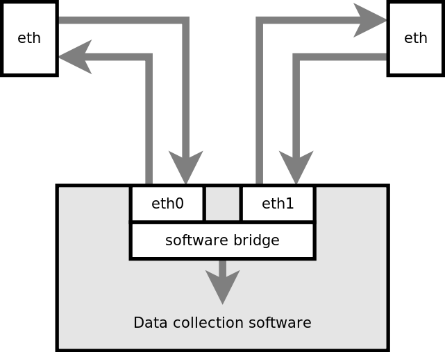
There are good things and bad things about this design. On the good side, it only requires standard hardware with no modification, and nearly any PC-style system can do it. On the bad side, it does interfere with the traffic, partly caused by the somewhat arbitrary time delay across the software bridge, partly because it tries to emulate a real switch, and further because sooner or later something will trigger the bridge to transmit additional packets into the network and reveal the fact that it is listening. Worse than that, it can't really do 100FDX because of the limitations of the bridging. Finally, something many people don't consider is that if the sniffer breaks down, or some software bug opens a security hole, then the link will be doomed. This may not even be directly a problem with the bridge, it could be any other software that happens to be on the same box, potentially causing a problem with the bridging.
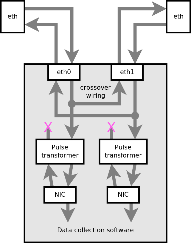
This block diagram gives the basic outline of the hardware modification below.
The hardware option used here is a Soekris net5501. You can buy them in Australia from Yawarra Information Appliances, or order them direct from Soekris in the USA. The net5501 has four Ethernet ports, each one using a different IRQ line (for better performance) and a 500MHz AMD Geode chip (not great, but good enough and runs at low power with neither heatsink nor fan).
The net5501 also has protection diode networks both before and after the transformer so this provides plenty of available space for wiring on top of the board, and it is easy to get to the tracks (which are also on the top of the board). Thus, it is reasonably easy to modify (if you have either good eyes or a microscope but that's true of all modern computer hardware).

In the photograph you can see one port wired to another port with fine wire wrap wire. Careful examination reveals that the polarity of each link remains consistent on either port (red is always on the left, blue on the right). The link between the ports is wired as a crossover, there are several reasons for this: it ensures that each signal goes to an RX circuit; and it means that external wiring for these ports will be identical as if the same ports were configured as a software bridge.
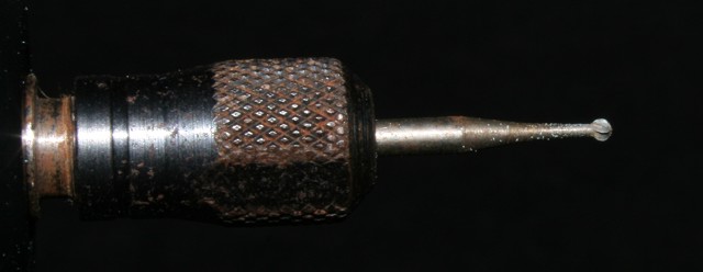
For cutting tracks, you can use either a knife, or a Dremel tool using a fine dentist-drill type of cutting bit.
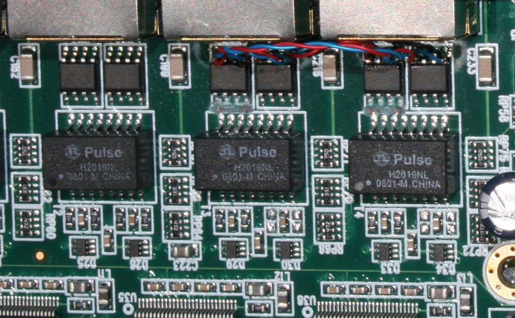
Most important is to ensure that the transmit circuits on the sniffer ports are completely disconnected from the cables. The best way to do that is to cut the track. The small pink "X" near the top (just above the "Pulse" transformer) shows where the tracks are cut (four cuts need to be made in total).
As well as cutting TX lines, it is also a good idea to remove the termination resistors on the RX circuit. These are just underneath the "Pulse" transformer, also marked with a pink "X". Termination resistors are each 50 ohm surface mount resistors, to a center tap. That makes a total of four resistors, working in pairs to provide 100 ohm termination for each of the RX circuits. As per the usual rule, termination must only exist at the ends of the circuit, since our receivers are the "man in the middle" in this configuration, the ideal situation is for this circuit to have no termination (and as little influence on the signal as possible).
A fine soldering iron is required to desolder these termination resistors. With care, they can be stored and replaced on the board at a future date if necessary. Note that the RX input the NIC chip itself loads the circuit with approximately 1k ohm due to its intrinsic input impedance. Although not ideal, the 1k impedance is ten times as big as the characteristic line impedance (100 ohm) and the proper termination impedance (also 100 ohm). This makes it unlikely to interfere with the signal, but in cases where the cables are long or otherwise near the limit, this problem may be noticable.
There is a handy program called mergecap, that merges two PCAP files together into a single output. This is a good way to put the whole conversation into a single file. There are times when you do not want to merge the traffic, such as when you have an ethernet broadcast (e.g. STP) and you are trying to figure out which side it is coming from.